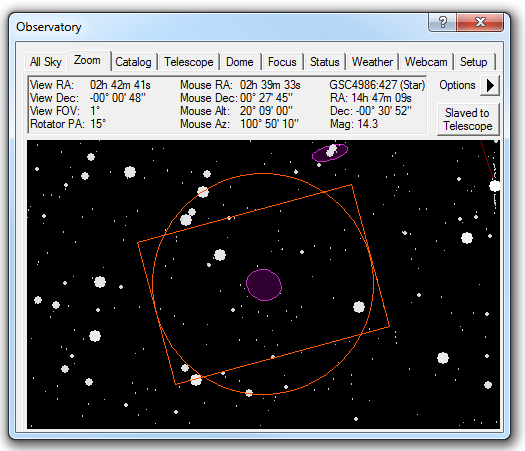
The Zoom tab provides a close up view of the sky. When the telescope is connected, it also shows a target at the current telescope position.
Along the top is a status display area. The first column shows the position of the current field center, the Field Of View (FOV) of the display (measured top to bottom), and if connected the Position Angle (PA) of the focal plane rotator. The second column shows you the position of the mouse in equatorial and local coordinates. The third column shows information when you click on an object in the display. Please note that you may need to expand the Zoom Tab window to see all of the information presented.

You can move the display by a variety of means. Click and drag on the star field to move the sky. You can use the mouse wheel to zoom in and out, or use the menus. The sky position can also be set from the All Sky Tab and Catalog Tab.
The Slaved to Telescope button will link the display to the current telescope position. The sky position will move if the telescope is moved. If you move the display manually the slave button will automatically disable.
The Options menu allows you to control the display:
Select either RA/Dec In JNow or RA/Dec in J2000 depending on which epoch you wish coordinates to be displayed in. Note that this does not affect how coordinates are transmitted to the telescope. Most telescope mounts operate in JNow coordinates, so depending on your settings the coordinates on the hand paddle may not exactly match the coordinates shown.
Find Scope Position takes you to the current telescope position, but does not lock the display to track the telescope.
Abort Slew will stop any telescope movement.
Move Rotator allows you to set the instrument rotator to any desired angle. You can also change the rotator angle by dragging the mouse between the two circles surrounding the displayed FOV indicator (see below).
Sync Rotator to Solved Image causes the angle reported by the rotator to be set equal to the "roll angle" of the currently selected image. This command is only available when the image has been solved astrometrically (see PinPoint Astrometry).
Overlay Image will check the currently selected image for astrometric WCS header information. If it is not present, the PinPoint Astrometry dialog will automatically be launched, which creates the necessary WCS header information. The image will then be overlaid on the sky display, precisely aligned with the stars and other symbols.
Auto Overlay Solved Images will overlay the currently selected image, as long as it has WCS header information. If you switch the selection between two or more images, the overlay will automatically switch between them.
Clear Overlay Image will remove the overlay from the sky display.
Zoom controls the zoom level of the sky display from 0.25 degrees to 30 degrees. You can also adjust the zoom level using the mouse wheel. Please note that you will need to configure the Guide Star Catalog in order for fainter stars to appear.
Density controls how many objects are displayed. This effectively adjusts the magnitude cutoff limit (for some objects a size limit is used instead).
FOV Indicators opens a submenu of commands to control a Field Of View indicator centered on the star chart. Use the Choose... command to define, select, and manage your Field Of View indicators; this is described below. Display shows or hides the currently selected FOV indicator without opening the configuration dialog. The remaining three entries specify the conditions under which MaxIm DL should display the FOV indicator rotated 180°: select Never Invert unless you are using a German Equatorial mount. In that case, select Invert on Telescope Pier Flip if you want the FOV indicator to match the orientation implied by the current telescope pointing angle, or pick Invert when Zoomed East for the orientation that would apply to an object if the telescope were looking at it in its current position in the sky.
Show Labels allows you to select the type(s) of objects for which labels are displayed.
Set Label Font allows you to set the font and size for labels, for each object type.
Flip X reverses the sky display horizontally. This may be used to match the star map orientation with the camera images. Note that Flip X and Flip Y together is equivalent to rotating 180 degrees.
Flip Y reverses the sky display vertically.
Set GSC Location allows you to choose the location of the Guide Star Catalog.
The Guide Star Catalog should be set up in order to ensure that plenty of stars are available at close-in zoom levels. The GSC is available on the MaxIm DL CD-ROM, or at http://gsc.dc3.com. For fast display it is strongly recommended that the GSC be copied to your hard drive. Both the GSC and TABLES folders are required; point the GSC Location to the folder above these two folders.
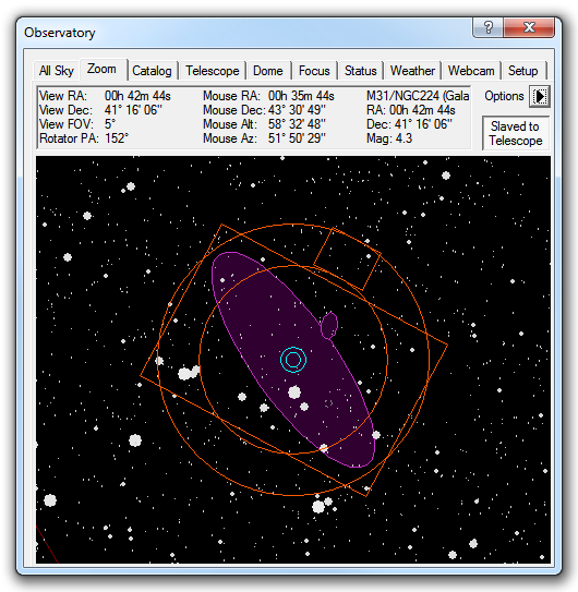
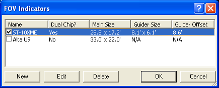
The FOV Indicators option allows you to configure overlays indicating the FOV of the camera. You can have several different indicators, but you can only select one for display at a time. To select an overlay, simply turn on the check box beside the Name.
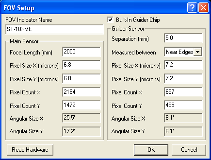
To create a new entry, click New. The FOV Setup dialog appears. Enter a name for FOV Indicator Name. Click the Read Hardware button (if a camera is connected) to enter the Pixel Size X (microns), Pixel Size Y (microns), Pixel Count X, Pixel Count Y, and Focal Length (mm). You can of course enter these values manually if desired. For cameras with integrated guide chips, you can turn on Built-In Guider Chip and enter the equivalent values for the guider. Separation (mm) can be specified as either the distance between the Near Edges of the two CCDs (outer edge of main sensor to inner edge of guide sensor), or between the Centers of the two chips; select the method you require using the Measured between control. In either case, the distance is specified in millimeters. (Changing the measurement method will recompute and update the separation if enough information is available to do so.) Click OK to add it to the list.
You can alter an FOV indicator by selecting it on the list and clicking Edit. You can also remove it from the list by clicking Delete. If you have a long list you can resize the dialog by dragging the lower right corner with the mouse. Click OK when you are done.
A right-click menu is also available when the mouse is positioned over the sky display. Many of the Options menu features are available here. There are also additional features:
Slew to Object slews the telescope to the named object, the one nearest the mouse cursor.
Slew to Mouse Position slews the telescope to the location of the mouse cursor.
The next two entries are checkable and apply when one of the above slew commands is issued:
Confirm Slew causes confirmation to be requested before a slew is performed.
Expose After Slew initiates an Auto Exposure when the slew completes. This command is slaved to the checkbox on the Telescope tab.
Sync to Mouse Position will display the Sync Telescope dialog.
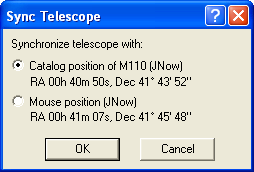
This allows you to reset the alignment of the telescope mount controller. You have the option of either synchronizing to the catalog object nearest the cursor, or synchronizing to the mouse position on the sky display.
Tip: The best method to align is to use PinPoint Astrometry to measure the exact location of an image from the camera, and then use the Telescope Tab Sync button, which allows you to synchronize to an image PinPoint solution.