For an introduction to this command please see CCD Basic Setup. DSLR users will want to review DSLR Exposure Control and DSLR Software Setup Tutorial. Also specific information for your camera model is available in the Camera and Autoguider Setup section.
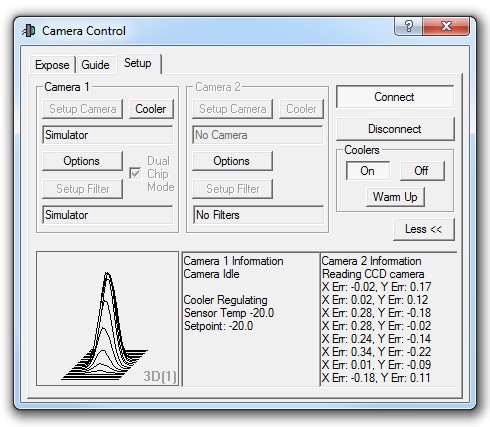
The Setup tab is used to initialize camera and filter wheel hardware, and control temperature regulation. Two cameras and associated filter wheels can be supported; normally one is operated as the main camera, and the other as the autoguider. The camera selection is made through the Expose Tab or Guide Tab.
Important: in most cases, you must install the drivers that were included with the camera by the manufacturer. While MaxIm DL includes many "plug-in drivers", most of these plug-ins operate through third-party drivers supplied by the manufacturer. In addition, many of the plug-in drivers themselves are supplied by the manufacturer; some of these are distributed with MaxIm DL as a convenience for the user, others are distributed directly by the manufacturer. For technical support related to software communications with a camera, you should first contact the camera manufacturer directly.

Setup for each camera or filter wheel works in much the same fashion. Click the appropriate Setup Camera or Setup Filter button to select and configure the hardware drivers.
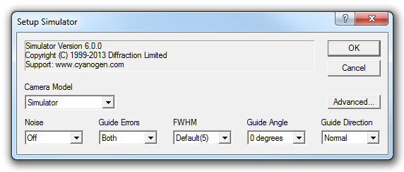
You can change the camera selection using the Setup Camera button. Various options will appear depending on what model is selected. Please see Camera and Autoguider Setup for information on specific models, or refer to the manufacturer's instructions if you are using a third-party plug-in driver.
You can configure two cameras, and each can have its own filter wheel. At any one time, one camera can be used as the main imaging camera, and one as the autoguider. These cameras can be the same brand or model; however, some camera manufacturers do not provide drivers capable of operating two cameras simultaneously. Also some cameras are not suitable for autoguiding due to their slow download speed or high shutter wear. In particular, DSLR cameras are not recommended as autoguiders.
Some cameras have dual imaging and autoguider capability, with either a built-in guide sensor, optional external guide head, or one-sensor interleave guiding capability (STAR2000). For these cameras, you should configure them as Camera 1, and then check Dual Chip Mode. This will indicate that the one camera head operates both a main and autoguider sensor. Camera 2 setup will be disabled, but the secondary sensor will appear as Camera 2 on the Expose Tab and Guide Tab.
Some camera models have the ability to output autoguider pulses to the mount through a special "ST-4" style cable. You can send the autoguider output through the main camera or the autoguider camera (regardless of which one is guiding), or via a large variety of other methods. Please refer to Guider Settings for more information.
Similarly if you are using filter wheel(s), they are configured using the Setup Filter button. Select the filter wheel model if the wheel is connected directly to the PC. If the filter wheel is controlled via a CCD camera, i.e. it is built-in or controlled through electronics in the camera head, select the appropriate camera model in the list. Please see Filter Wheel Setup for information on configuring specific models.
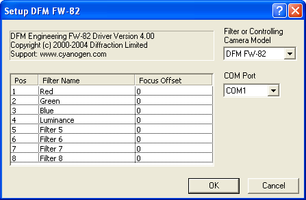
The names for each filter slot can be specified under Filter Name. Click once on the row to highlight the row, then click once on the Filter Name to edit it. If your filter wheel has fewer slots than allowed for by the driver, simply leave the extra slots blank; they will not appear in the drop-list filter selectors.
If the filters vary in thickness, a Focus Offset can be entered for each filter. This causes the focus position to be offset appropriately every time an exposure is taken with a new filter position. The offset is expressed in focuser steps. If this feature is used, absolute positioning focusers are strongly recommended to ensure repeatability. To set up the offsets, first record the optimum focus position for each filter (Autofocus is ideal for determining this). Pick one filter as being the "zero" filter, and subtract its position from the others. Then enter the resulting numbers into the appropriate Focus Offset fields. Now whenever a filter is selected, the appropriate offset will be used to adjust the focuser position.
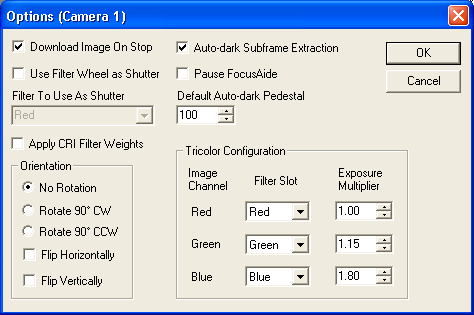
Click the Options button on the Setup tab for either Camera 1 or Camera 2 to select among the following additional options:
When Download Image On Stop is checked, clicking the Stop button on the Expose Tab will cause the image to be read out and displayed as if the exposure had terminated normally, instead of being discarded. If the camera plug-in does not support this behavior or the camera is being used as a guider, this control is ignored.
If your camera does not have a mechanical shutter, you can block one position of your filter wheel and have MaxIm DL interpose it automatically when exposing a dark frame. Click Use Filter Wheel as Shutter and then select the opaque position from Filter To Use As Shutter.
When Auto-dark Subframe Extraction is checked, MaxIm DL always acquires full-frame darks for calibrating Simple Auto-dark exposures; if it is necessary to calibrate a subframe, the corresponding part of the full-frame dark is extracted and used. For some cameras, these do not accurately match real subframes, and in this case you should turn this option off.
Pause FocusAide disables focuser movements by the third-party focusing tool FocusAide during CCD image download. This applies to both the main camera and autoguider. Some CCD camera drivers disable interrupts during download, which can cause erroneous focuser motion if FocusAide is actively moving the motor. This option will have no effect if FocusAide is not present or inactive.
Default Auto-dark Pedestal specifies the constant added to the difference of a Simple Auto-dark exposure and its corresponding dark. This is usually set to 100, but can be increased to avoid clipping with noisy cameras. For low-noise 8-bit cameras, you may want to reduce it.
Set the Apply CRI Filter Weights option when using a CRI tunable filter. This causes exposures taken with Readout Mode "Color" to use a special 3x3 matrix that produces an image with a more accurate color representation.
The Orientation controls enable automatic rotation and/or reflection of images when they are downloaded from the camera. Select one of No Rotation, Rotate Image 90° CW (clockwise), or Rotate Image 90° CCW (counterclockwise). You can also check either or both Flip Horizontally (left-right) or Flip Vertically (top-bottom); selecting both is equivalent to a 180° rotation. Note that guider calibration must be repeated after any change in Orientation settings.
The Tricolor Configuration controls are applicable if you are using a monochrome camera with a filter wheel. For each Image Channel, select the appropriate Filter Slot and specify an Exposure Multiplier. For example, if your blue filter requires twice the exposure time of your red filter to achieve the same signal level, you could enter 1.00 for Red and 2.00 for Blue. These settings are used when you use the Auto-Tricolor option of the Main Camera.
Once the equipment has been selected and configured, click the Connect button to initiate links to the hardware. An error will be produced if any hardware fails to connect; if so, all links will be disconnected.
Once the camera(s) are connected, you may need to set up the cooler. Most scientific-grade CCD cameras have closed-loop cooler systems that can be set to a particular temperature. Under Coolers click On to start the cooler(s). If control is available, you can then use the Cooler buttons for the main camera and autoguider to set the temperature.
If cooler control is not available, the camera status will say "No cooler control". This is not an error message. Some camera models, including Starlight Xpress and Orion StarShoot cameras, have unregulated coolers; the cooler will be operating normally but you cannot control it.
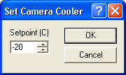
If you do have temperature control, dial in the desired cooler temperature Setpoint (C) and click OK. Note that the cooler temperature should be set as low as possible without exceeding the camera’s cooling capacity. There should be a bit of room at the bottom to allow for proper temperature regulation. Some camera models will automatically back off if they cannot reach the desired temperature.
If a camera’s cooler is already on when you connect to the camera, the three cooler control buttons will pop up. This is done because the main camera and autoguider may not be in the same state; it is reminding you to set up the coolers.
When you prepare to shut down, the first task is to warm up the cooler(s). Click the Warm Up button to start the cameras warming up. The period of time required for the warm-up depends on the particular camera model; some cameras simply turn off the cooler, while others gently raise the cooler temperature over a period of time. If you need to switch off the cooler rapidly, click Cooler Off to immediately power down the coolers.
Please note that in rare cases switching the cooler off suddenly could result in thermal shock, which if done repeatedly could eventually affect camera reliability. Despite popular belief, thermal shock is rare and is only a long-term reliability risk for cameras that have extremely high delta-T capability. Many popular models warm up slowly even if you pull the power plug. Nevertheless, it is prudent to warm the camera to above freezing before shutting down the cooler completely.