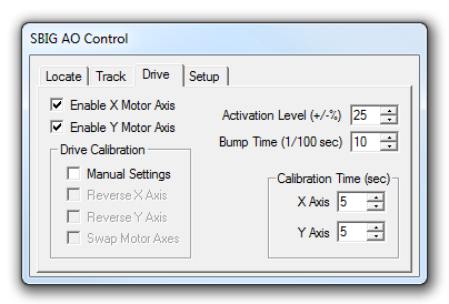
The Drive tab is used to set up the motor drive for autoguider operation. Unlike normal autoguiders, the AO tip/tilt optic will be doing most of the corrections while autoguiding. The motor drive will only be activated occasionally. This means that the exact calibration speed is unimportant; only the directions must be set correctly.

The Enable X Motor Axis and Enable Y Motor Axis check boxes determine whether the mountís drive motors will be used to apply additional, automatic corrections in the X and Y directions when drift exceeds the AO unitís abilities to guide out. Individual selectors are useful if, for example, the mount can only be controlled in Right Ascension. Turn off both these fields to completely disable mount control. This can be done if the mount tracking is sufficiently accurate or if the user manually adjusts the mount (while monitoring the optic position with the Track tab).
The motor directions Reverse X Axis and Reverse Y Axis can be automatically set using the Calibrate Drive mode on the Locate tab. However the directions can be set manually if the Manual Settings check box is checked. The Swap Motor Axes check box is turned on when the X axis of the autoguider image corresponds to the Y correction axis. Assuming the X axis relay controls the Right Ascension axis, the check box is turned off when the camera is oriented so that North or South is at the top, and on when East or West is at the top. This check box is also automatically set by the Calibrate Drive function.
The Calibration Time determines the length of time for which the Calibrate Drive operation activates the motors. If the Calibrate Drive operation reports that the guide star has not moved sufficiently or has moved off the frame during the calibration adjust these values accordingly.
The Activation Level sets the point at which the main telescope drive will begin correcting. The optic starts at the 50% (centered) position. Setting an Activation Level of (+/-) 10% will cause drive corrections to start when the optic reaches either 40% or 60% deflection, depending on which way it is drifting. If the Activation Level is set to 50% (i.e. 100% optic deflection) the motor drive will never be bumped.
The Bump Time specifies the number of centiseconds (hundredths of a second) for which the motor drive is actuated when a bump occurs. If you enter 10 as the Bump Time, the motor is activated for 0.1 seconds.
Please note that the method used to send bump commands to the mount is selected using Guide tab Settings Control Via.